Posts

Showing posts from September, 2020

What is a thyristor | Construction | Working | Advantage and disadvantage | Application

Image
INTRODUCTION -  Thyristor is unidirectional like a diode that allows flow of current only in one direction. In contrast to diode, thyristor can attenuate the forward current until its is set off by an appropriate gate signal among gate and cathode terminal. Image source - Google | Image by - Pixabay Thyristor is also called "SCR" (Silicon Control Rectifier) because As silicon is used for construction and it is operated as a controlled rectifier i.e very low resistance in forward direction and very high resistance in reverse direction. Construction of Thyristor - Thyristor is a 4 layer , 3 Junction , with substitute layers of p-type and n-type materials. it has three terminals Anode(A) terminal , cathode(K) terminal , and Gate(G) terminal. Image source - Google | Image by -  Wikimediacommmons The terminal associated with external p-type material is called anode(A). The terminal connected to the outer n-type material is called cathode(K).Gate terminal is usually kept near the c...

What is 555 timer (part-2)

Image
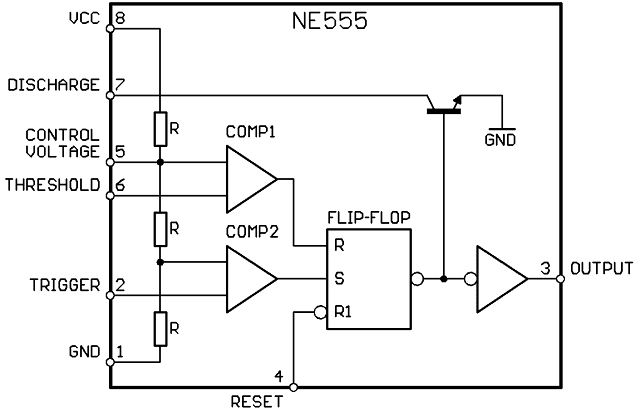
Function of 555 timer-   So, by this threshold voltage, we are controllingthe output voltage. And same is true with this trigger pin. So, let's say, the voltage at this threshold pin is less than (2/3)Vcc voltage. That means the output of the first comparator is low voltage. Now, whenever this trigger signal goes below this (1/3)Vcc voltage, then the output of the second comparator will become high. So, in this case, S will become 1 and R willbe equal to zero. So, this flip-flop will get set to the logic1. And in a way, the output will also get set to the logic 1. Image Source - Google | Image by -  wikimediacommmons So, using these threshold and trigger pins actually we are controlling the output voltage. And in a way, we are controlling the timing of this output signal. So, to change the input voltage to this threshold pin, the external resistor and the capacitors are connected between this threshold and the discharge pin through the supply voltage. And the same is true with...

What is 555 timer (part-1)

Image
Introduction to 555 timer -   555 timer ic is extremely mainstream ic and it is helpful in the circumstance related applications. Presently, this 555 timer ic is accessible in endless bundles. But here we are going to talk about the 8pin DIP package. Image source - Google   | image by - snappyGoat   Pin Diagram- if you see the pin diagram, then the pin diagram will look like this. And here is the corresponding name of each pin. Along these lines, we should quickly observe the depiction of eachpin and how about we additionally observe the inside square chart of this 555 timer.So, this is the internal block diagram ofthis 555 timer ic.The first one is the voltage divider circuit. Then the next block is the comparators. And if you see, the output of the comparatoris going to the flip-flop circuit. The flip-flop is the third block. Image Source - Google | Image by - wikimediacommmons there is a discharge circuit for the discharging purpose. And then after the last block is...

Popular posts from this blog

CODING-DECODING

What is a thyristor | Construction | Working | Advantage and disadvantage | Application